
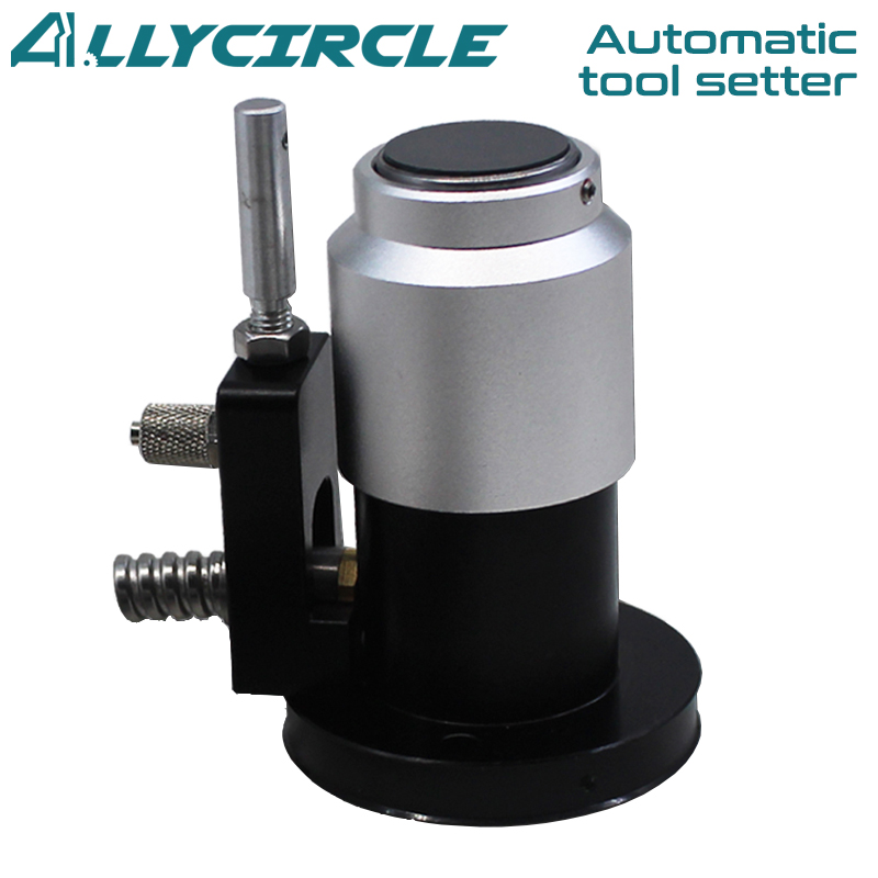


Engraving machine automatic tool setter
—High precision automatic tool setting—


Super cost-effective!
7 major advantages in one
High-precision automatic tool setter
* High accuracy
* Oil and Waterproof
* Easy to install
* One year warranty
* Lightning delivery
• Repeated tool setting accuracy of 0.001mm
• Repeat tool setting 3 million times

Product parameters

The dimensions are all measured manually, there is a 1-2mm error, for reference only.


4 major advantages and quality cast
Dustproof and waterproof Durable

No need for a built-in amplifier

Alarm Timely reflection

High accuracy Strong anti-interference

Two types
1.Normally closed type
4 wires circuit diagram

2.Normally open types
6 wires circuit diagram

Product description
1. Contact should not exceed the travel of the tool instrument, otherwise the tool instrument and the tool will be damaged;
2. Do not let go immediately when touching the contact surface of the tool tester, so as not to damage the internal structure of the tool tester.
3.When the tool and tool instrument contact the end of the tool, vertical lift away from the contact surface, do not move horizontally, if longitudinal movement will damage the tool.
Product Installation Instructions
1. Please try to install it on the workbench where there is less iron filings and splash water; The contact surface
between tool and tool counter must be installed vertically, and contact with the contact surface vertically downwards to ensure that the bottom is flat to avoid large precision error.
2. Please be sure to use within the rated voltage range, voltage control DC24V, current below 20MA, ambient temperature range 0~80° C.
3. The tool diameter should be controlled below 20MM, the tool speed should be controlled at 50-200mm /MIN, and the tool center should be in the center of the tool surface.
4. be sure to power off before installation, after wiring is completed, the tool tester will be placed in another place of the tool holder, test the tool signal is normal and then fix the correct position.
Product Installation Instructions


PROFESSIONAL CONSULTATION
If you are interested in our products and want to know more details, please leave a message here, we will reply you as soon as we can.